2

This seems like an ideal place to ask a question that has been keeping me confused for a little while now. But I apologize if I've posted in the wrong area.

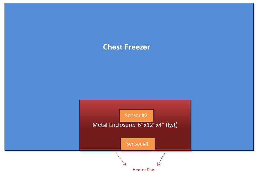
My question is that I don't seem to understand the temperature trend that I am seeing from my temperature sensors. I'll start of with my setup: Essentially, I have a metal box with two temperature sensors. 1) Is mounted right at the base of the box [Temp Sensor #1] 2) The second temperature sensor is mounted 2 inches from the top of the box [Temp Sensor #2]. The box is about 6 inches in height.

I've placed a heating pad at the base of the box (Temp Sensor #1 lies right in the center of this pad. A graphic showing my setup:
I've also implemented a simple on/off temperature controller, that senses when the temperature goes above a certain set-point and turns off (hence you see the highs/lows for Temp Sensor #1).
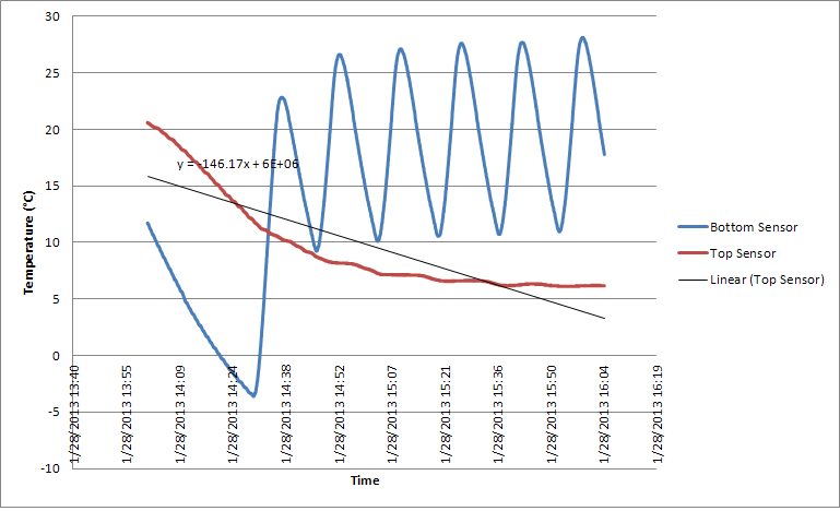
As you can see from the image, the lower sensor (blue) has the peaks/troughs corresponding to when the heater turns on/off. The heater gets triggered every time the sensing temperature goes below the set point. What I don't understand is why the top sensor (red) has a periodically decreasing trend (it doesn't have highs/lows similar to the bottom sensor)? It doesn't seem to be affected by the heater turning on at all? Even though it is merely 4" away from the heater inside the metal enclosure.

I understand that Sensor#1 is probably changing immediately due to the heater very quickly affecting the metal base temperature via conduction. Whereas the second sensor is probably measuring the air around the metal enclosure at the top, and since air is an insulator, it takes longer to heat up. But there should be at-least some highs and lows I'd imagine. The continuous decreasing trend doesn't make any sense ...

Then, I suspected that perhaps my second temperature sensor was damaged. But that wasn't the case. I've tested both sensors and they work fine. Also here is a graph of the temperature trend, when I place the enclosure (with the sensors) in the freezer with no heater action. Intuitively as you can imagine, there is merely a decreasing trend for both sensors (shown below) due to the effect of the freezer:

Any suggestions please as to why I notice no temperature variation at Sensor #2 location when the heater turns on/off?

4
  • Here is the trend with no heater and the freezer merely cooling: i47.tinypic.com/2430vp2.png , I couldn't post it in the original post since I do not have sufficient rep points. The heater pad type, I am using is this: winemakersdepot.com/Brewers-and-Wine-Making-Heat-Pad-P700.aspx
    – c0d3rz
    Commented Jan 31, 2013 at 0:32
  • 1
    I see when the heater is turned on an off, but when is the cooling activated?
    – mdma
    Commented Jan 31, 2013 at 1:32
  • What temp are you trying to stabilize at and is this metal enclosure insulated? Especially the lid.
    – brewchez
    Commented Feb 2, 2013 at 22:19
  • You've also inappropriately applied a linear fit to data that isn't behaving that way. You state that its a continuous decreasing trend. But it isn't, it has stabilize half way through the data collection period.
    – brewchez
    Commented Feb 2, 2013 at 22:24

1 Answer 1

1

It's to do with thermal inertia. If you look closely at the graph you'll see there are highs and lows for sensor #2 also - just much smaller than sensor #1, and they have the same period (time interval) as sensor #1, indicating they stem from the same heating oscillation.

You're of course right when you say that air is a poor conductor, and so it will essentially dampen the effect of the heater - there are rises and falls, just over a smaller, dampened range.

I'm not entirely clear on when the freezer switches on and why it would be on when the heater is also on, but it seems that's the case from the graph. Another reason for the imbalance is that the freezer has a far greater cooling effect than the 25W heater can heat. Most freezers are in the order of 120W or more, and have a Coefficient of Performance (CoP) of 2 or more when chilling to beer temperature, so you're getting about 240W of real cooling power vs 25W of heating power (resistance heating has a CoP <= 1) - so a 10:1 difference.

I imagine the main reason you're seeing any fluctuation in sensor 2 at all is because of the box, which confines the convection of heated air to within the box. I imagine if you removed the box and did the same thing, you'd see very little change in sensor #2 because of the large volume of cooler air surrounding it.

4
  • Hi mdma: The freezer is always switched on, it is never turned off. Also, I'm using a 120W heater instead, so the heating/cooling difference is not that large I think. If I go with the idea of thermal inertia, why is that the lower sensor (Sensor #1) changes so quickly then? Shouldn't it face the same problem?
    – c0d3rz
    Commented Jan 31, 2013 at 2:56
  • 1
    The lower sensor changes quickly because the rate of conduction through contact with #1 is much quicker than conduction through the air to #2.
    – mdma
    Commented Jan 31, 2013 at 2:59
  • Hmm, just one last question about this CoP. Why is that the CoP is greater than 1 in the case of cooling?
    – c0d3rz
    Commented Jan 31, 2013 at 20:59
  • The CoP for compressor/inverter systems like fridges and heating pumps because they are just moving heat from one place to another, so the net heat output can be higher than the energy consumed. With a resistance based heat pad, this turns electrical energy into heat, and so the amount of heat produced can never be more than the electricity consumed.
    – mdma
    Commented Jan 31, 2013 at 21:09

Your Answer

By clicking “Post Your Answer”, you agree to our terms of service and acknowledge you have read our privacy policy.

Not the answer you're looking for? Browse other questions tagged or ask your own question.